
The 20-Minute End-Fed Half-Wave: A Garage-Built Antenna That Punches Above Its Weight
The first antenna I bought for POTA cost me $75 and worked fine. The second antenna I built in my garage for about $18 in parts worked better. I'm not saying that to sound clever — it's just how it went, and it's a pretty common story. The end-fed half-wave antenna is one of the most forgiving, portable, and genuinely effective antennas you can put up in a park. And if you build your own, you'll know exactly what's in it, which pays off every time something needs to be troubleshot.
Here's how to build one in about 20 minutes. I mean that literally — if you've got the parts on hand, I've timed it.
Why the EFHW Works So Well for Portable
The end-fed half-wave is resonant on a specific band (or its harmonics) without needing a tuner. A wire cut to half-wavelength on 40m — about 66.5 feet — is also resonant on 20m, 15m, and 10m. That means one antenna covers four bands, which is a big deal when you're trying to stay light and fast. You feed it at the high-impedance end (roughly 2,500-5,000 ohms) through a 49:1 transformer that steps the impedance down to something close to 50 ohms that your radio can see.
The alternative — a center-fed dipole — is great but requires a feedpoint in the middle of the wire, which complicates deployment. An EFHW lets you run all your coax back to the operating position and mount the transformer at the base of your mast. Much cleaner setup when you're working solo.
One thing to understand: the EFHW needs a counterpoise. Not a big one — typically 0.05-wavelength is enough, which on 40m is about 3 feet. A lot of commercial EFHW designs use the coax shield as the counterpoise, which works reasonably well if your coax is at least 20-30 feet. A small wire counterpoise clipped to the transformer chassis ground lug is more predictable and something I'd recommend adding if you're building from scratch.
Parts List
Everything you need for the transformer and feedpoint:
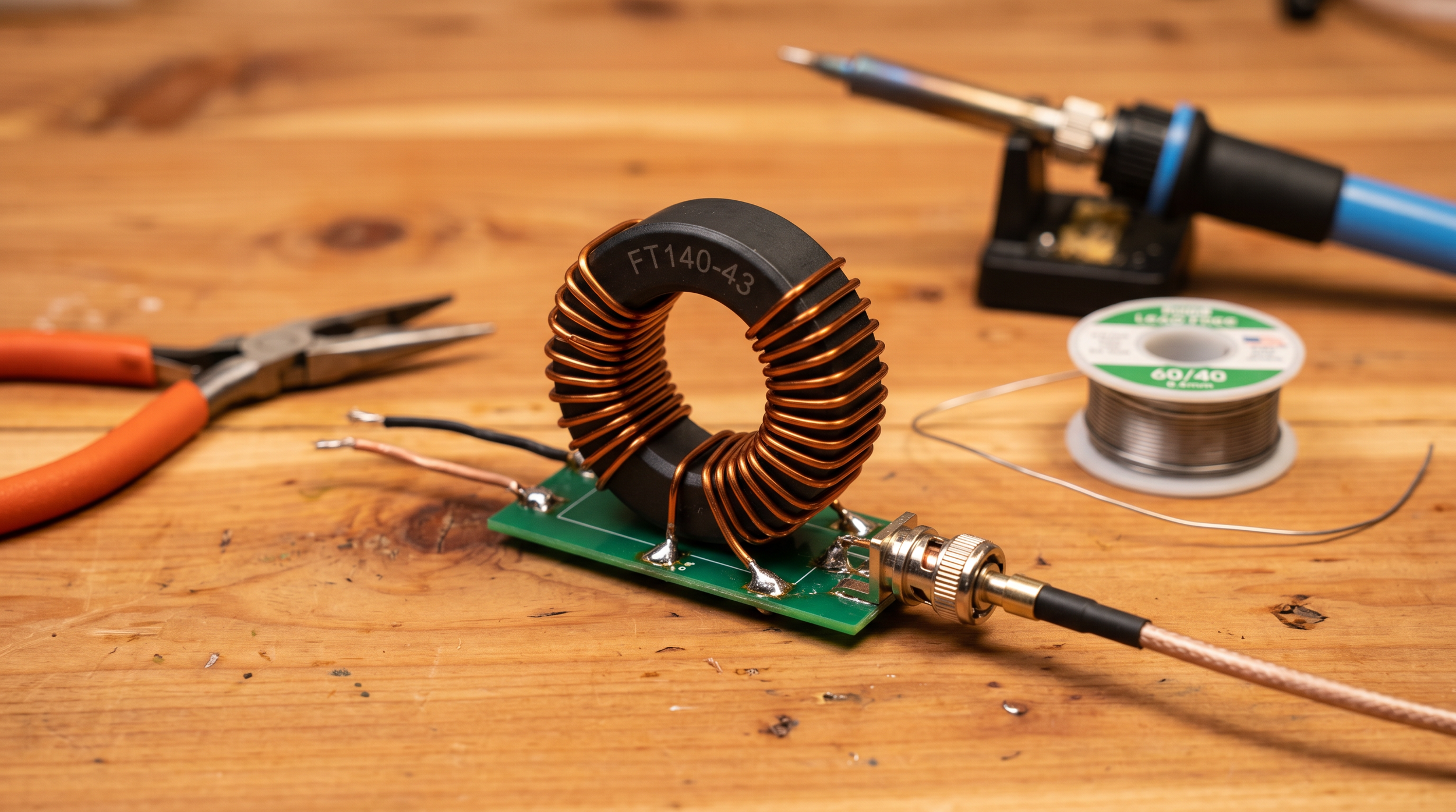
1x FT140-43 ferrite toroid core (about $5-7 from Mouser or KitsAndParts)
26 AWG or 24 AWG magnet wire (enameled copper), roughly 6 feet — you likely have this already
Enclosure: a small Hammond 1590A die-cast aluminum box ($5-8) or a PVC project box
SO-239 chassis connector for the radio side ($2-3)
Wing nut or binding post for the wire connection
1/8" stainless bolt + nut for the counterpoise lug
Small capacitor, 100pF 500V (optional but recommended — improves 10m performance noticeably)
For the wire:
66.5 feet of 26 AWG stranded hookup wire or antenna wire for 40m resonance (cut slightly long, then trim)
For a lighter build, some people use 28 AWG — fine for 100W if you don't run it into high SWR
Total cost in parts: roughly $15-20, depending on what you already have.
Winding the 49:1 Transformer
The 49:1 ratio comes from a turns ratio of 7:1 — 7 turns on the primary (radio side), 49 on the secondary (antenna wire side). On an FT140-43 core, the winding process takes about 10 minutes if you're patient.
Primary Winding
Strip and tin your 24 AWG magnet wire. Wind 7 turns through the center of the FT140-43 core. A "turn" means the wire passes through the hole once — count hole passes, not wraps around the outside. Space the turns evenly and keep them tight against the core. Connect one end to the center pin of your SO-239 and the other end to the ground lug.
Secondary Winding
For the secondary, you need 49 turns. This sounds tedious, but it isn't bad on the FT140-43, since the core is large enough to accommodate the wire comfortably. Use the same 24 AWG wire. Wind in the same direction as the primary. One end goes to the antenna wire connection (binding post or wing nut), the other end goes to ground, same as the primary cold end. The shared ground point between primary and secondary is important — don't skip it.
The Optional Capacitor
Solder a 100pF 500V capacitor across the primary (between the center pin and ground on the SO-239 side). This resonates out some of the transformer's leakage reactance at 10m and 15m and measurably improves your SWR on those bands. It doesn't affect 40m or 20m performance. Worth doing while you've got the iron out.
Enclosure and Finishing Up
If you're using a Hammond 1590A box, drill a hole for the SO-239, a hole for the antenna wire to exit, and a small hole for the counterpoise connection. Use a chassis punch or a step drill bit. Mount the SO-239, run the transformer inside, and secure the core with a small dab of non-conductive epoxy or a zip tie through a cable clamp — you don't want the toroid bouncing around inside the box over rough terrain.
Seal the antenna wire exit with a grommet or a dab of silicone to keep moisture out. Label the box with a marker: band, transformation ratio, and build date. You'll thank yourself in 18 months.
For the wire itself, I use 26 AWG silicone wire — it's flexible, doesn't retain a memory set in the cold, and coils neatly onto a fishing winder or a small cord winder. The silicone jacket is also noticeably tougher against bark and branches than standard PVC hookup wire.
Installing and Testing
Before you go to the park, hook a NanoVNA to the SO-239 and sweep 7 to 30 MHz with the antenna wire deployed (or at least fully extended in your garage or yard). You're looking for the SWR dip on 40m to land somewhere in the 7.000-7.300 MHz range, and dips on 20m, 15m, and 10m that correspond to harmonics.
If your 40m dip is below 7.0 MHz, the wire is a little long — trim 6-inch increments from the far end, re-measure, repeat. If the dip is above 7.3 MHz, the wire is short, and you'll need to add a few inches. This tuning process is genuinely satisfying — you're watching the antenna respond to physical changes in real time.
What "Good Enough" SWR Looks Like
At the 40m dip, you want SWR below 1.5:1 without a tuner. Below 2:1 is acceptable if you've got an internal tuner in your radio. If you're seeing 3:1 or worse with the wire fully deployed, double-check that both the primary and secondary cold ends are properly grounded to the same point — that's the most common winding error.
How It Performs in the Field
Honest answer: It performs like a real antenna. I've made contacts on 40m SSB into the Pacific Northwest from New Hampshire on 100W with this antenna, slung at about 25 feet on a crappie pole. The 20m performance is excellent — the EFHW's harmonic resonance on 20m is genuine, and you don't take a big efficiency hit.
Compared to a commercial antenna like the PAR EndFedz or the LNR Precision Trail-Friendly end-fed, a good homebrew 49:1 on an FT140-43 will hold its own. The FT140-43 core handles 100W without heating up under normal operating conditions. I've run a continuous 5-minute carrier at 100W during testing, and the core stayed barely warm. For POTA-style operating — short transmit bursts, long receive windows — heat is essentially a non-issue.
Watch & Learn
If you want to see the EFHW concept in action before you start winding, here's what to queue up:
- [BEST portable QRP antenna (JUST OK MINI)](https://www.youtube.com/watch?v=6rVIJCYvbDY) — a hands-on look at portable antenna performance in the field, including how EFHW-style antennas compare to alternatives
- [POTA Tips, Tricks & Hacks (N1JUR)](https://www.youtube.com/watch?v=4eRNNE5tLfw) — antenna deployment tips baked into a broader activation walkthrough
Go Build It
Honestly, the hardest part is ordering the toroid. Once the FT140-43 shows up in your mailbox, you'll have the thing wound, tested, and ready to go in an evening. And there's something satisfying about making 40 contacts on an antenna you built yourself for less than the cost of lunch.
Questions about winding, enclosures, or matching — come find me in the Brew & Activate Discord at [discord.gg/zwg9mWyHmY](https://discord.gg/zwg9mWyHmY). The build-your-own-antenna crew in there is genuinely helpful and not snobby about it. More antenna content and activation guides over at [n1jur.com](https://n1jur.com).